|
THE SURFACE CARBURETTOR
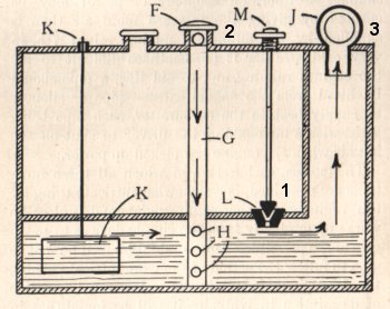
What is known as a "surface" carburettor is simply a tank as described, but in which arrangement is made for drawing the incoming air either over or through the petrol. The above figure shows about the most simple form of surface carburettor; the diagram is a section of a tank such as might be found on a motor bicycle. It will be seen to be divided by an inner partition; this upper and inner portion provides the petrol storage, the under part being the carburettor proper. Petrol is admitted from upper to lower compartment at intervals as required by turning the milled nut M, which actuates the conical valve L, which is shown open, the carburettor working best when the petrol is about the level shown, at which point the valve should be closed until the float rod K shows that more petrol is required. The air supply comes in through holes F in the air-shaft which passes through the petrol tank and to the bottom of the carburettor, a series of holes H H H being drilled at the lower end. The air admitted at F may be controlled by a revolving cap more or less covering up to the holes. As the engine suction draws in air it flows out of the holes H H H and bubbles up to the surface of the petrol highly charged with vapour, passing along the surface of the petrol up the side shaft to the mixing chamber J. It should also be observed that the whole of the petrol surface is covered by air which becomes richly charged with vapour by the time it reaches J, which is a double cylinder with closed ends but communicating in the centre, one cylinder communicating with outer air and the other with the supply pipe to engine. Holes cut in the top of the tank and in the outer casing of the twin tap or mixing chamber J, afford communication through the two cylinders, actuated by small levers. The first of these may be termed the "quality" chamber, and at opposite diameters holes are drilled at the top of the tank and the top of the casing, in which the cylinder is movable. At the portion of the cylinder surface covering these holes a slot as wide as the holes is cut away through nearly half the diameter of the cylinder, so that when in one position the slot in cylinder coinciding communicates with the outer atmosphere and maximum quantity of air would be drawn in, at the same time the gas outlet from carburettor would be almost closed, giving the minimum amount of gas. By drawing back the lever the air-hole is decreased in area and at the same time the gas outlet is enlarged; thus a fine regulation of the proportion of gas and air is obtained. The other half of the cylinder is in communication with the tank by means of holes corresponding in size, so that by a forward of backward motion of the controlling lever these holes may be made to more or less coincide or be shut off from communication altogether. This is best described as the "quantity" tap, dealing as it does with the quantity of already correctly-mixed explosive which is is allowed to pass onward to the engine. _________________________ MINERVA TWO-SPEED GEAR
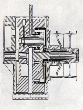
Attached to the big end of the connecting rod is a small pinion A. This engages with an internal toothed ring B, the flywheel C being recessed to take the latter. It will therefore be seen that the internal toothed ring B and the flywheel are always revolving in the same direction at two different speeds. A hollow shaft D, fixed to the internal toothed ring B, is carried to the exterior of the crankcase E, and a solid shaft F attached to the flywheel C runs through the hollow shaft D. Fixed to each shaft is a pulley H, H1 to take a flat belt. To change speed, the belt is slipped by a lever from one pulley to the other. The width of the rim pulley on the driving wheel of the machine equals the width of the two engine pulleys, so as to ensure the belt always running in line. The control of the two speeds is by means of a Bowden wire operated from the handle-bar.
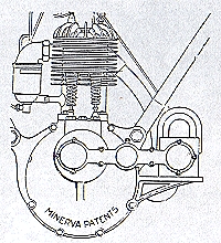
HIGH TENSION MAGNETO IGNITION (rotary) WITH MINERVA PATENT TRANSMISSION
This comprises an EISEMANN high tension
magneto fitted with the Minerva patent transmission. The magneto dispenses with
accumulator and contact breaker. An alternating current is produced by the
magneto and is transformed into high tension current by a coil. An ordinary
sparking plug is used and the timing of the ignition can be advanced or retarded
in the usual way. A bracket is attached to the crank case in front of the motor
supporting the magneto which is driven by the Minerva patent transmission. The
present methods of giving the rotary movement between engine and magneto, viz.,
chain or gear wheels have in many cases proved a source of trouble and
inconvenience, both in the fitting, appearance, noise, and lubrication. The
Minerva patent transmission overcomes all such difficulties, is readily fitted,
requires no adjustment, has no dead point, and ensures accurate and smooth
running of the magneto.
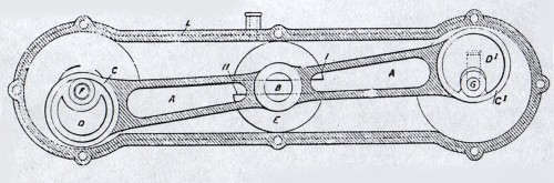
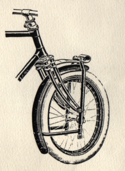
Description: The transmission consists of a connection rod A carrying in its centre a slide B, and on both its extremities and eccentric strap C and C1. Two eccentrics D and D1 are fitted, one on the half speed shaft F of the motor, the other on the magneto shaft G, and are coupled together by means of the connecting rod. The slide B is running in a guide E compelling the connecting rod, when the device is working, to travel with its centre between H and I, thus doing away with the dead point existing in ordinary connecting rods. The guide E is fitted in the aluminium case I, which covers the whole device, preserving it from dust and dirt, and ensuring perfect lubricating. All that is necessary to fit the transmission is to remove the commutator complete, and screw into its place the aluminium case carrying the eccentrics. One eccentric takes the place of the ignition cam, and is fixed to the half speed shaft - the other end of the case is attached in a similar manner to the magneto, the eccentric being attached to the magneto shaft. This transmission and magneto can be supplied with the 2 3/4, 3 1/2 and 4 1/2 hp motor cycles. _________________________ MINERVA SPRING FORK
Minerva spring fork |